The Logic NOR Gate gate is a combination of the digital logic OR gate and an inverter or NOT gate connected together in series.
The inclusive NOR (Not-OR) gate has an output that is normally at logic level “1” and only goes “LOW” to logic level “0” when ANY of its inputs are at logic level “1”. The Logic NOR Gate is the reverse or “Complementary” form of the inclusive OR gate we have seen previously.
Logic NOR Gate Equivalent

The logic or Boolean expression given for a logic NOR gate is that for Logical Multiplication which it performs on the complements of the inputs. Its Boolean expression is denoted by a plus sign, ( + ) with a line or Overline, ( ‾‾ ) over the expression to signify the NOT or logical negation of the NOR gate giving us the Boolean expression of: A+B = Q.
Then we can define the operation of a 2-input digital gate as being:
“If both A and B are NOT true, then Q is true”
Transistor Logic NOR Gate
A simple 2-input logic gate can be constructed using RTL Resistor-transistor switches connected together as shown below with the inputs connected directly to the transistor bases. Both transistors must be cut-off “OFF” for an output at Q.

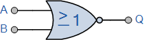
Logic NOR Gates are available using digital circuits to produce the desired logical function. It is given a symbol whose shape is that of a standard OR gate with a circle, sometimes called an “inversion bubble” at its output to represent the NOT (Inversion) gate symbol as shown:
The Digital Logic NOR Gate
2-input Logic NOR Gate
| Symbol | Truth Table | ||
 2-input NOR Gate 2-input NOR Gate | B | A | Q |
| 0 | 0 | 1 | |
| 0 | 1 | 0 | |
| 1 | 0 | 0 | |
| 1 | 1 | 0 | |
| Boolean Expression Q = A+B | Read as A OR B gives NOT Q | ||
3-input NOR Gate
| Symbol | Truth Table | |||
 3-input NOR Gate 3-input NOR Gate | C | B | A | Q |
| 0 | 0 | 0 | 1 | |
| 0 | 0 | 1 | 0 | |
| 0 | 1 | 0 | 0 | |
| 0 | 1 | 1 | 0 | |
| 1 | 0 | 0 | 0 | |
| 1 | 0 | 1 | 0 | |
| 1 | 1 | 0 | 0 | |
| 1 | 1 | 1 | 0 | |
| Boolean Expression Q = A+B+C | Read as A OR B OR C gives NOT Q | |||
As with the OR function, the NOR function can also have any number of individual inputs and commercial available IC’s are available in standard 2, 3, or 4 input types. If additional inputs are required, then the standard NOR gates can be cascaded together to provide more inputs for example.
A 4-input NOR Function

The Boolean Expression for this 4-input NOR gate will therefore be: Q = A+B+C+D
If the number of inputs required is an odd number of inputs any “unused” inputs can be held LOW by connecting them directly to ground using suitable “Pull-down” resistors.
The Logic NOR Gate function is sometimes known as the Pierce Function and is denoted by a downwards arrow operator as shown, A↓B.
The “Universal” NOR Gate
Like the NAND gate seen in the last section, the NOR gate can also be classed as a “Universal” type gate. NOR gates can be used to produce any other type of logic gate function just like the NAND gate and by connecting them together in various combinations the three basic gate types of AND, OR and NOT function can be formed using only NOR gates, for example.
Various Logic Gates using only NOR Gates

As well as the three common types above, Exclusive-OR, Exclusive-NOR and standard NOR gates can also be formed using just individual NOR gates.
Commonly available digital logic NOR gate IC’s include:
TTL Logic NOR Gates
- 74LS02 Quad 2-input
- 74LS27 Triple 3-input
- 74LS260 Dual 5-input
CMOS Logic NOR Gates
- CD4001 Quad 2-input
- CD4025 Triple 3-input
- CD4002 Dual 4-input
7402 Quad 2-input Logic NOR Gate

Leave a Reply